Properly Sequencing Multiple IC Supply Voltages on a System Board
投稿人:电子产品
2012-06-12
Modern electronic system boards require multiple non-isolated point-of-load (POL) regulators to power numerous ICs such as microprocessors, memory, logic, and so on. Many of the ICs require multiple voltages. For instance, microprocessors need 1.8 V or less for the core and 2.5 V and more for the I/Os. While providing these multiple voltages, system designers must also ensure that the voltages are in proper sequence during the power-up and power-down phases. In fact, there are three different types of sequencing solutions: sequential, ratiometric, and simultaneous.
The designer must either use a separate circuit to properly coordinate and sequence all the voltages on the board during power-up and power-down modes or use regulator modules with built-in sequencing capability.
Sequencing techniques
Before applying any one of the three sequencing techniques, the user should have a basic understanding of each method and know when to use one versus the other two. An application note¹ (AN04-008) generated by GE Energy (formerly Lineage Power) entitled, “Guidelines for Sequencing of Multiple Modules,” provides that help, briefly discussing all three sequencing techniques.
Figure 1 depicts the sequential method described in the app note. In this scheme, the core voltage often comes up first and reaches its final regulated value during power-up. This is followed by the second voltage, shown in Figure 1 as VI/O, which reaches its final value after a specified delay. During power-down, the sequencing order of the supply voltages is reversed.
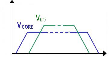
Figure 1: Voltage waveforms for sequential startup.
The second technique is called the ratiometric sequencing approach, wherein both of the supply voltages reach the regulation point at the same time. However, as shown in Figure 2, the core and I/O voltages have different slew-rates to enable both voltages to reach their regulation point at approximately the same time. During ratiometric power-down, both output voltages start ramping down at the same time instant, but with different slew-rates, so that they reach zero at approximately the same time.
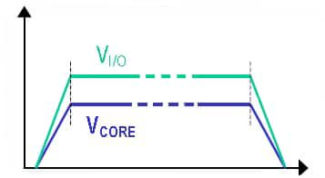
Figure 2: In ratiometric sequencing, both supply voltages reach regulation point at the same time.
The third sequencing method is the simultaneous startup or voltage tracking. Here, both voltages start ramping up with identical slew rates. After the core or lower voltage reaches its regulation level, the I/O voltage continues with the same slew-rate until it reaches its own regulated voltage (Figure 3). This arrangement is reversed during power-down sequencing.
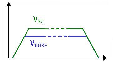
Figure 3: In simultaneous sequencing, both supply voltages start ramping with identical slew rates.
Design examples
Power supply manufacturers like GE Energy offer non-isolated point-of-load (POL) converter modules with a built-in sequencing feature, which GE calls EZ-SEQUENCE. GE Energy offers several product lines that incorporate this extra level of flexibility to power loads that require a precise sequencing of voltages during the power up and down phases. Three GE series with the built-in EZ-SEQUENCE feature include TLynx, Austin Lynx II, and Austin MegaLynx. This sequencing feature helps engineers implement any of the three types of the sequencing previously discussed.
The ON/OFF control present in all TLynx modules can be used to turn them on and off in a desired sequence using an external logic control. It is generally used for implementing the sequential method of sequencing. Usually, the logic level signal is referenced to the converter’s ground pin. Also, depending on the type of the non-isolated POL module, the logic can be either positive or negative for remote ON/OFF control.
For implementing the ratiometric or simultaneous/tracking methods of sequencing, more precise control of the timing and slope of the output voltage during start-up and shutdown is required. Consequently, this function is implemented through an additional pin called SEQ. When a voltage is applied to the SEQ pin, the output voltage tracks this voltage on a one-to-one basis until the output reaches the set-point voltage. This allows the output voltage to be brought up in a controlled manner as long as the final value of the SEQ voltage is made higher than the set-point voltage of the module.
The circuit configuration for ratiometric sequencing is presented in Figure 4. As shown, proportional voltages on the SEQ pins result in two different output slew-rates, with each module reaching its set-point voltage at approximately the same time instant.
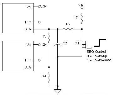
Figure 4: Ratiometric sequencing is achieved by applying control voltages proportional to nominal output voltages to power modules SEQ pins.
The ratiometric startup sequence with control voltages on the SEQ pins and the resulting output voltages with identical rise times are plotted in Figure 5.
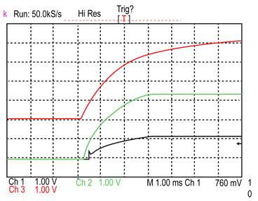
Figure 5: Scope plot for ratiometric start-up of two modules in Figure 4. The upper waveform shows the tracking voltage while the two lower waveforms are the output voltages.
The app note referenced¹ also provides circuit configurations for simultaneous start-up of three modules. In this simultaneous sequencing, the circuit uses the highest voltage output module as the control voltage on the SEQ pin of the other modules. This ensures that all the outputs track the highest voltage until their set-point voltage. The ON/OFF pins of the lower output modules are tied to ground or left open to keep the modules on by default as the output of these modules is now controlled through the SEQ pin.
In summary, board designers need to not just provide multiple voltages, but also to ensure proper voltage sequencing for each multi-voltage IC during power-up and power-down. A built-in voltage sequencing feature like EZ-SEQUENCE in power modules makes the job easier for system power designers. By use of the sequencing pin and the circuits shown in the example discussed, all three types of sequencing—sequential, simultaneous/tracking, and ratiometric — can be supported.
Reference
- Application Note ANAN04-008 Guidelines for Sequencing of Multiple Modules; Lineage Power (Now GE Energy)
免责声明:各个作者和/或论坛参与者在本网站发表的观点、看法和意见不代表 DigiKey 的观点、看法和意见,也不代表 DigiKey 官方政策。


 中国
中国