


How to Optimize Energy Use in IoT Edge Devices
投稿人:DigiKey 北美编辑
2018-05-01
When designing battery-powered Internet of Things (IoT) devices, a prime objective is to extend the time between recharges, or in the case of standard cells, the lifetime of the battery. There are many traditional approaches, but these lack the necessary system level perspective needed to fully optimize a design.
For maximum use of available battery power, the IoT device needs to be optimized as an entire system and not as a collection of unrelated components. This article will examine the latest techniques and technologies available to optimize an IoT design’s energy consumption and how best to apply them.
Traditional approaches to measuring energy
The general embedded systems developer is no stranger to optimizing their system for battery life. In the good old days, developers would often use a multimeter such as the B&K Precision BK2706 to measure the current consumption of their embedded system. These are great multi-meters and can certainly be used to measure average current, but won’t give a developer the resolution they need to see fast spikes or measure current consumption down into the microamp range without considerable effort. In order to see these fast transitions, a developer needs something fast that they can easily trigger.
An oscilloscope, coupled with a shunt resistor sized for the current range, can be used to see these fast current transitions. A developer might use something like the BK2190, also from B&K Precision. This is a great low-cost 100 MHz oscilloscope. A developer can certainly trigger the scope to see spikes and transitions, but there are still several challenges with using an oscilloscope in this particular application.
First, most low-cost oscilloscopes won’t allow a developer to easily get access to the trace. Second, the trace is limited in its recording length. Third, the oscilloscope data can’t be synchronized to events that are happening on the embedded system. Considering all three issues, a developer could struggle to optimize their IoT device within the project timeline. Therefore, a new and more modern approach is necessary to effectively optimize an IoT device’s energy consumption.
Optimizing energy consumption using a smart power supply
One new and more modern way that an IoT device can be optimized is to use a smart power supply that not only supplies energy to a device, but also has the ability to measure the voltage and current that is being supplied to that device. A smart power supply could be looked at as a hybrid between a power supply and a data acquisition system.
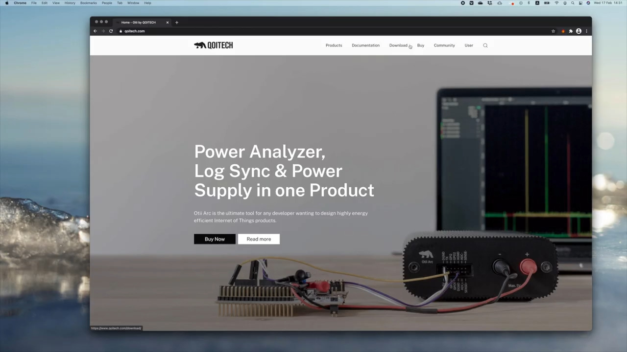
One such power supply is Qoitech AB’s Otii Arc. This is a portable power supply that also acts as a current and voltage measurement unit. It is used to power an IoT device whose energy profile needs to be optimized. It transmits its collected data to a PC over USB. The Otii Arc can also be powered via USB.

Figure 1: The Otii Arc from Qoitech AB is a portable power supply that also acts as a current and voltage measurement unit. (Image source: Qoitech AB)
The Otii Arc can be configured through its otii software package to supply anywhere from 0.5 to 5.0 volts. When using a USB port to power the Otii Arc, a maximum output of 250 milliamps (mA) can be delivered. For most IoT devices this would be more than sufficient, but for developers working on systems that are more power hungry, an external 7.5 volt to 9.0 volt power supply can be used to achieve currents up to 2.5 amps (A) continuous with a maximum peak current of 5.0 A. The Otii Arc can also sample at up to 4 Ksamples/s at current resolutions as low as 1 microamp (µA), which is sufficient for most IoT devices.
Using the Otii Arc
An IoT device under test (DUT) can be connected to the Otii Arc in several ways. In the first method, just like with most power supplies, there are two banana jack plugs for supplying power to the device. This allows a developer to use a 12” red banana cable from Pomona Electronics, with red Pomona grippers to supply the voltage rail. A 12” black Pomona banana cable with black Pomona grippers is used to supply the ground rail. This is a standard setup for any embedded system engineer’s bench.
The second method uses the Otii Arc’s 14-pin expansion header with 0.100” pin spacing. This expansion port has useful connections such as a second analog-to-digital converter (ADC) channel for measuring current, GPIO pins, and even serial transmit and receive pin signals.

Figure 2: Connect to the Otii Arc using the standard banana jacks that are on nearly every power supply. Developers can use 12” red Pomona Electronics banana cable and red Pomona grippers to connect the positive voltage rail to their IoT device under test. (Image source: Pomona Electronics)
The Qoitech Otii Arc comes with a standard license for the otii software, a visualization tool that interfaces to the Otii Arc to perform current and voltage measurements and control the power supply’s behavior. The visualization is used to analyze energy consumption and determine where and how to optimize the system.
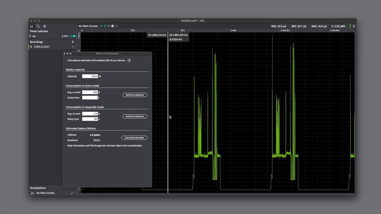
The otii software connects over USB to the power supply and can be used to enable and disable the supply voltage or record a trace. When tracing, a developer can see the live trace which provides a strip chart type view that is easily navigable. Developers can highlight regions in their trace and be provided important information such as the minimum, maximum, and average current (Figure 3).

Figure 3: When tracing with the Otii Arc’s otii software, a developer can see the live trace, which is shown in a strip chart view that is easily navigable. (Image source: DigiKey)
As discussed earlier, it is often critical that a developer be able to understand the system state at various points in the trace so that they get a single, coherent source of information that they can analyze. It’s important that a smart power supply also be able to receive log inputs from the embedded system that can be used to synchronize the state.
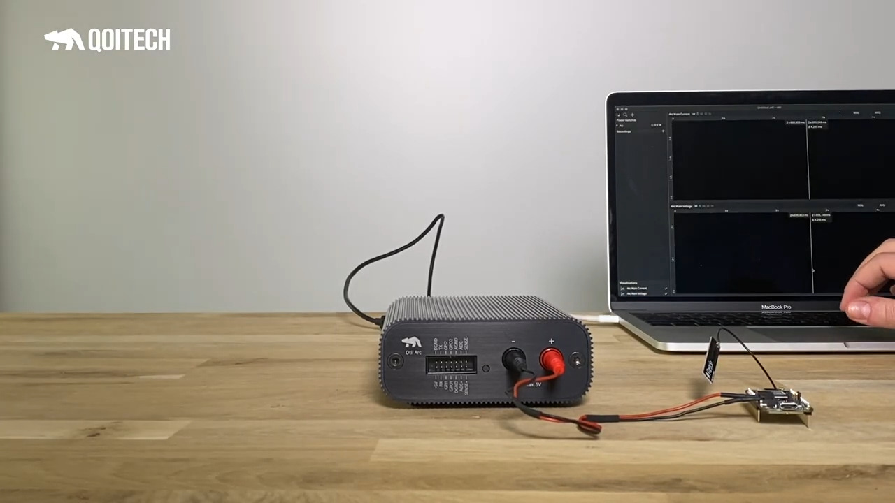
What’s also interesting about the Qoitech Otii Arc is that the expansion connector has the ability to read in a serial UART at a configurable baud rate and record that log information in the trace. Setting up a system to transmit the execution log involves receiving a string log over a UART from the embedded target. To do this, connect the UART Tx pin on the IoT device to the Rx pin on the Otii Arc (Figure 4). It’s good practice to also connect a digital ground to the IoT device to ensure that the signals share the same ground reference.

Figure 4: To receive a string log over a UART from the embedded target, connect the UART Tx pin on the IoT device to the Rx pin on the Otii Arc. (Image source: Qoitech AB)
To demonstrate how data is recorded in the otii software, an LED is shown toggling and providing a log status over UART to aid the developer (Figure 5).

Figure 5: The Otii Arc can be set up to receive UART log messages that can assist a developer in understanding what state the embedded system is in. In this example, an LED is toggling and providing a log status over a UART to aid the developer. (Image source: Qoitech AB)
Optimizing subsystem energy usage
There are several ways to use a smart power supply to optimize a device’s energy consumption, but they do require some forethought. For example, a developer should include multiple shunt resistors on their pc board so that they can connect and probe the energy consumption of different circuits. Failing to do so will only provide a developer with the overall system current, which can make optimization more of a guessing game than an engineering activity.
Developers can use the expansion ADC to monitor an external shunt resistor. This resistor could be monitoring a Wi-Fi module, a memory chip, or the microcontroller itself. This feature allows a developer to tune an individual circuit while monitoring how the overall system energy consumption is affected. All a developer needs to do is set the shunt resistor value in the project settings of the otii software and the correct currents will be recorded in the trace (Figure 6).

Figure 6: The Otii Arc can be set up to record the system voltage and current, along with a second current shunt of a subsystem. This allows a developer to tune a specific circuit while simultaneously monitoring how the overall system energy consumption is affected. (Image source: Qoitech AB)
One of the biggest energy consumers in many battery-powered IoT systems will undoubtedly be the microcontroller. A smart power supply can be used to monitor the microcontroller, but in many cases a developer will want to be able to synchronize their current measurements with the program counter in the microcontroller. This allows the current consumption to be synchronized with the lines of code that are being executed.
To do this, a developer can use a smart power supply in conjunction with an advanced debugger such as Arm’s Keil ULINKplus, which has the ability to measure microcontroller current and synchronize that measurement with the program counter. Then, when a developer takes all these measurements together, they will be able to finely tune their energy consumption and maximize their IoT design’s battery life.

Figure 7: The Arm Keil ULINKplus can be set up to record microcontroller current usage and synchronize that measurement with the lines of code that were executing on the microcontroller. This helps to provide a full picture of the IoT devices energy usage. (Image source: DigiKey)
Tips and tricks for optimizing IoT system energy consumption
There are several tips and tricks that developers can follow in order to easily optimize their embedded systems for energy consumption. These include:
- For each major hardware block in the design, add a shunt resistor that can be used to monitor that circuit’s energy consumption during development and testing.
- Read “Select and Apply the Right Low-Power Microcontroller for the IoT” for tips on how to measure and optimize microcontroller energy consumption.
- Put major system components into their sleep mode or low power state as often as possible.
- Measure energy consumption throughout the entire development cycle and not just near the end.
- Use an energy analyzer that can cover the applications dynamic range.
- Automate as much of the measurement process as possible.
- In hardware, look for inefficient and leaky components such as LDOs and replace them with more efficient ones.
Conclusion
Optimizing any IoT device for energy consumption is not a trivial endeavor, and it is especially important for battery-powered devices. As shown, there are several traditional methods for measuring energy consumption. Having the right tools to make appropriate measurements can make it easier to identify energy hogs and design IoT solutions that make the best use of available battery power.
免责声明:各个作者和/或论坛参与者在本网站发表的观点、看法和意见不代表 DigiKey 的观点、看法和意见,也不代表 DigiKey 官方政策。


 中国
中国