What You Need to Know About Modulators and Demodulators
投稿人:电子产品
2013-03-14
Modulation, in the context of RF applications, refers to the mixing of two sinusoidal signals. An RF modulator is a device that takes an input signal and outputs a modulated signal. Modulators have basically two inputs and one output. One input is usually known as the ‘information’ input. The other input is the RF carrier input.
The output signal is a composite of the two input signals. For example, in a DVD player, modulators convert signals to a format that acceptable for use in a television receiver.
Demodulators, on the other hand, take the modulated signal and output the information signal and the carrier signal. The carrier signal does not get further used. In a system, the modulator is placed before the transmitter while the demodulator comes after the receiver.
Whether the signal is voice or data, various modulation techniques are available such as analog modulation (AM, FM) and digital modulation (frequency shift keying or FSK, amplitude shift keying or ASK, and phase-shift-keying or PSK).
In amplitude modulation (AM or ASK), the amplitude of the carrier varies in accordance to the information signal. In frequency modulation (FM or FSK), the frequency of the carrier varies in accordance to the information signal. In phase modulation (PM), the phase of the carrier varies in accordance to the information signal.
ASK can also be combined with PSK to create hybrid systems, such as quadrature amplitude modulation (QAM), where both amplitude and phase are changed at the same time.
All have their pros and cons. ASK, for example, is simple to employ, but can be susceptible to noise. FSK is less susceptible to noise, but (in theory at least) requires a larger bandwidth/bitrate than ASK.
Similarly, PSK is less susceptible to noise and is bandwidth efficient, but requires synchronization in frequency and phase and therefore complicates receivers and transmitter design.
Numerous choices
Modulators and demodulators can be found in military, wireless, and broadband communications applications. Manufacturers of these devices include Analog Devices, Hittite Microwave, Linear Technology, NJR, Skyworks Solutions, Texas Instruments, Freescale Semiconductor, NXP, and ON Semiconductor.
Distributors and manufacturers try to ease the designer’s task of choosing the right modulator or demodulator by offering a parametric search engine on their websites. For example, typing in modulator demodulator into the DigiKey parts search engine allows the designer to filter results by:
- Manufacturer
- LO frequency (0 Hz to 6 GHz)
- RF frequency (0 Hz to 6 GHz)
- P1dB (-30 dBm, -22 dBm, 3 dBm)
- Gain (-1.3 dB, -0.7 dB, -0.5 dB, 2 dB)
- Noise figure (4 dB, 6.8 dB, 9.9 dB)
- Current supply (11 mA, 32 mA, ... 370 mA)
- Voltage supply (1.8 to 20 V)
- Package/case (14-DIP (0.300 in., 7.62 mm))
- Supplier device package (14-DIP, 14-DMP)
- Packaging (cut tape, Digi-Reel®, and tape and reel)
Analog Devices’ ADL5375 (Figure1) is a broadband quadrature modulator designed for operation from 400 MHz to 6 GHz. Its excellent phase accuracy and amplitude balance enable high performance intermediate frequency or direct radio frequency modulation for communication systems.
The part’s high dynamic range across this frequency range is a key attribute for direct up conversion transmitter architectures. It also combined the highest linearity with 24 dBm output IP3, the highest linear output power with +10 dBm P1dB, and a low 161 dBm/Hz noise floor. The ADL5375 also offers unadjusted sideband suppression of –55 dBc and unadjusted carrier feed-through of –41 dBm – eliminating the need for calibration circuitry among the most demanding of applications within cellular radios.
This device allows the user to shut down the transmitter, further simplifying receiving of small signals in time division applications such as WiMAX and TDS-CDMA.

Figure 1: Analog Devices 400 MHz to 6 GHz ADL5375 transmit quadrature modulator.
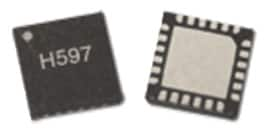
The HMC597LP4E SiGe wideband direct conversion I/Q demodulator from Hittite Microwave (Figure 2) is suited for high linearity communications receivers. The device directly converts an RF signal into I and Q baseband signals with up to 600 MHz bandwidth. This part is optimized for receivers operating from 100 to 4,000 MHz in a wide range of applications including cellular, RFID, test equipment, and broadband wireless infrastructure.

Figure 2: Hittite’s HMC597LP4E SiGe wideband direct conversion I/Q demodulator.
This highly integrated device has an on-chip RF balun. A single off-chip capacitor allows the reconfiguration of the RF port to operate over the 100 to 4,000-MHz band without the need for additional off-chip components. Other notable specifications include +25 dBm IIP3 and +60 dBm IIP2 at 1,900 MHz with a local oscillator drive level of 0 dBm. It also has a LO-to-RF isolation of 66 dB, a noise figure of 15 dB at 1,900 MHz, and a current consumption of only 200 mA from a 5 V supply. This part is ideal for software radio and other multiband receiver applications.
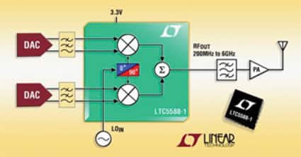
A popular part from Linear Technology is the 200 to 6,000 MHz LTC5588-1 (Figure 3) quadrature modulator with an ultra-high OIP3 (Output Third-Order Intercept). This part offers 30.9 dBm OIP3 at 2.14 GHz (without calibration). It has the unique capability for simple calibration by a single-pin adjustment with a DC input voltage that further optimizes its OIP3 up to 35.1 dBm. This linearity performance is complemented with a noise floor of –160.6 dBm/Hz at 6 MHz offset. These performance features enable transmitters to achieve unprecedented dynamic range performance.

Figure 3: Linear Technology’s quadrature modulator.
Additional specifications include an image suppression of –56.6 dBc at 2.14 GHz and carrier leakage of –39.6 dBm while delivering 5 dBm signal power to its output without calibration.
The LTC5588-1’s I and Q inputs are biased to a 0.5 VDC common-mode voltage that is directly compatible with commercially available D/A converters that have similar DC common-mode voltage. The I and Q inputs support signal bandwidth greater than 400 MHz.
Housed in a compact 4 x 4 mm, 24-pin QFN package, the LTC5588-1 is powered from a 3.3 V supply with an operating current of 300 mA. The part has an Enable pin, which allows the chip to power down completely. In shutdown mode, the chip draws a sleep current of less than 900 µA.
For more information on the parts mentioned in this article, use the links provided to access product information pages on the DigiKey website.
免责声明:各个作者和/或论坛参与者在本网站发表的观点、看法和意见不代表 DigiKey 的观点、看法和意见,也不代表 DigiKey 官方政策。


 中国
中国