


Simplified Topology is Key to Solar PV Microinverter Design Reliability
投稿人:电子产品
2011-08-17
Microinverters offer distinct advantages in flexibility, efficiency, and safety for solar photovoltaic (PV) panels, but cost-effective options have been limited in the past. In designing microinverter modules today, however, engineers can confidently rely on a broad range of solutions for implementing alternative inverter topologies that improve module efficiency, reliability, and cost. Microinverter module designers can choose from a variety of power components, integrated devices and specialized microcontrollers from parts manufacturers including Analog Devices, Fairchild Semiconductor, Littelfuse, Microchip Technologies, National Semiconductor, and Texas Instruments.
Conventional solar PV installations feed DC voltage to a central inverter for conditioning and distribution locally or across the power grid. Aside from the operational risk of this single point of failure, one shaded, dirty or malfunctioning panel can erode the efficiency of the entire array. Furthermore, the DC voltage carried through the array to the central inverter carries significant fire and safety hazards, leading to increased costs for cabling and, in turn, higher costs for installation and maintenance.
To mitigate individual panel effects, solar PV designers have moved power conversion to each individual string, or set of series-connected panels in a large array. String converters, or optimizers, provide DC-DC conversion to enhance power delivered to the central inverter by each string. This approach reduces the impact of a single poorly-performing panel to its string rather than the entire array. But such installations still need to contend with the hazards and costs associated with DC voltage transmission. Ultimately, however, the need to rely on a central inverter leaves a critical single point of failure with this approach.
String inverters eliminate the need for a central inverter by providing DC-AC conversion at the output of each string. By eliminating the central inverter and its potential as a single point of failure, this approach improves system robustness. The use of AC voltage transmission helps reduce fire and safety hazards—simplifying installation and maintenance of large arrays. As with string converters, string inverters offer incremental improvement in overall array efficiency compared to conventional central inverter installations, yet still permit a single degraded panel to have an unduly large impact on overall output.
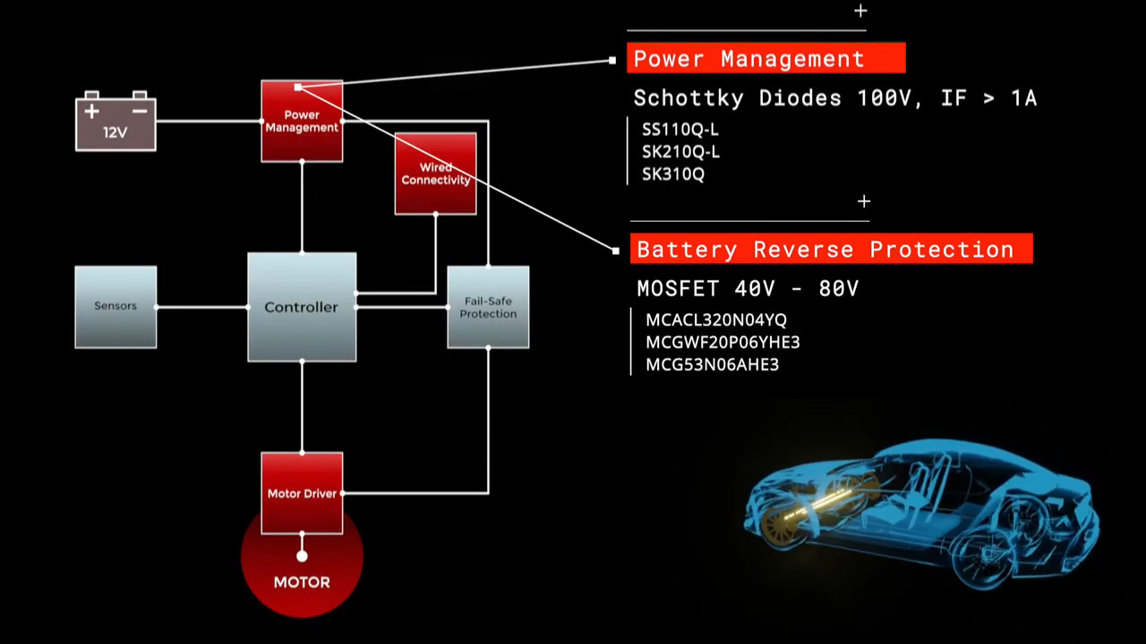
Microinverters take the concept of string inverters to the next level - providing DC-AC conversion from each individual panel rather than an entire string. Introducing critical circuitry on the panel itself brings additional concerns for reliability, cost and complexity. Indeed, microinverters share the same requirements as larger central inverters but can safely employ components with lower ratings for use with individual PV panels (Figure 1). At the basic component level, engineers need to ensure signal integrity and isolation, using parts such as P6KE transient voltage suppression (TVS) diodes from Fairchild Semiconductor, Littelfuse, Vishay, and others, to isolate downstream paths from high-voltage transients including lightning strikes.

Figure 1: Whether intended for per-panel microinverter applications or central inverters, inverter design depends on a broad array of functional elements tied to improving the efficiency of DC-DC converter and DC-AC inverter. (Source: Analog Devices).
At the higher systems level, microinverter design calls for real-time execution of a number of precise algorithms for efficient DC-AC conversion, circuit protection and PV panel power optimization through maximum power-point tracking (MPPT). MPPT is essential to maintain the optimum panel loading required to sustain the best possible power output from the panel served by each microinverter module.
The key algorithms for these tasks are typically available in proven software libraries that complement digital signal controllers and microcontrollers with integrated peripherals such as the Analog Devices ADuC7128 microcontroller, the Microchip Technology dsPIC33F digital signal controller, and Texas Instruments' TMS320F28x digital signal controller, among others. The availability of integrated peripherals, including analog to digital converters (ADCs) and pulse-width-modulated outputs (PWMs), allow these controllers to directly sense inputs and precisely control power MOSFETs in bridge circuits, improving overall efficiency while reducing parts count and module size.
Exposed to the environment, the microinverter requires the same kind of circuit protection required in central inverters but with even more reliable circuit components able to withstand extremes in temperature and humidity. At the same time, microinverter design requires the smallest, most cost-effective BOM possible to minimize cost, weight, and volume in the final modules attached to each PV panel. Consequently, some of the most efficient inverter multi-stage topologies with relatively high BOM counts might not be practical. Instead, microinverter designs tend to rely on simpler one- or two-stage inverter topologies.
Single-stage microinverters boost the panel voltage and shape the AC waveform output in a single stage (Figure 2). This approach results in the lowest possible component count, while simplifying isolation. Its disadvantages include high voltage ratings on both the primary side switches and the secondary side diode, as well as high amplitude ripple current on the input, which would lead to power loss without the use of large electrolytic capacitors on the microinverter input. This electrolytic capacitor required for power decoupling between the PV panel and grid tends to be the limiting component for module reliability. Ripple current in the electrolytic capacitor produces heat, raising temperature in this component and further reducing its lifespan.

Figure 2: A single-stage microinverter performs DC boost and AC waveform inversion in a single stage. The use of the interleaved flyback topology shown here reduces ripple current, improving lifespan of the electrolytic capacitors typically limited in this type of design. (Source: Microchip Technology).
The use of an interleaved flyback converter topology shown in Figure 2 helps improve the lifespan of the capacitor by reducing ripple current. The interleaving action of this approach also reduces current total harmonic distortion of the output current. In a grid-tied installation, engineers also need to measure grid characteristics to properly synchronize microinverter output to the grid and handle islanding, or isolation of the module in the event of loss of connection to the grid due to external events such as power failures.
Along with this single-stage design, the two-stage topology is a suitable candidate for microinverter circuits (Figure 3). Built around an intermediate high-voltage DC bus, this approach boosts input PV voltage to the intermediate-bus voltage. A conventional pulse-width modulation inverter then puts the final shaped AC waveform on the output. This approach results in significantly lower input ripple current at the PV input, permitting use of lower capacitance components such as high reliability film capacitors rather than electrolytic capacitors.

Figure 3: The two-stage topology uses an intermediate high-voltage DC bus to connect the separate stages for DC-DC conversion and DC-AC inversion. The National Semiconductor SM72295 controls the process by providing precise gating signals to the four MOSFETs on the primary side. (Source: National Semiconductor).
As with any inverter design, both of these microinverter topologies rely on efficient IGBT or MOSFET devices such as the STMicroelectronics STH260N6F6 DeepGATE MOSFET or Fairchild Semiconductor FDMS86200, among others. Precise gating of these power components is increasingly managed by controllers and specialized devices, including the National Semiconductor SM72295 – one device among several in the company’s extensive SolarMagic family of parts intended specifically for solar PV design. Capable of driving all four MOSFETs in the primary side full-bridge, the SM72295 provides two high-side and two low-side gate drives as well as integrated bootstrap diodes. The device can handle input voltages up to 100 V and provides signal conditioning, undervoltage lockout and overvoltage shutdown. Other devices in the SolarMagic family provide gate drive functionality, voltage regulation, sending, and MPPT control.
Designing a cost-effective microinverter presents multiple challenges not only in DC-DC conversion and DC-AC inversion but also in ensuring efficient energy utilization. Available power components, integrated devices, and microcontrollers provide the parts needed to design highly efficient solutions based on single- or two-stage inverter topologies.
免责声明:各个作者和/或论坛参与者在本网站发表的观点、看法和意见不代表 DigiKey 的观点、看法和意见,也不代表 DigiKey 官方政策。


 中国
中国