


Reducing Wearable Health and Fitness Device Design Time
投稿人:DigiKey 北美编辑
2017-04-11
The wearable health, wellness, and fitness market is extremely fast-moving, with new products appearing almost weekly. The availability of low-cost, low-power microcontrollers and widespread wireless connectivity have helped spur a drive towards portability and the growth of a new market in personal fitness monitors.
For a design team, developing a new health or fitness device often means compressing functions that formerly resided in a piece of bedside equipment into a size that’s easily portable, or can even be strapped around a wrist. The speed of the market also poses problems: spending months to evaluate devices and develop custom hardware to validate a concept may cause a new product to be late, or even miss the market window entirely.
This article will look at examples of two common wearable health devices and identify their shared sensing, processing and communications features. It will then introduce and show how to get started with a reference design platform that features these necessary characteristics and solves many of the design issues associated with a wearable device.
Examples of portable medical devices
What components form the heart of these portable medical and fitness designs? Let’s look at a couple of examples:
Pulse oximeter: A pulse oximeter measures oxygen saturation in arterial blood to ensure that there is sufficient oxygenation: users include persons with respiratory problems, patients undergoing anesthesia, and premature or newborn babies (Figure 1).

Figure 1: A typical finger-mounted pulse oximeter, one of many health-related wearables. (Image source: 911school.com)
A pulse oximeter is non-invasive. The most common sensing method measures the oxygen level by transmitting red and infra-red (IR) light through a finger, toe, or ear, and measuring the ratio of the two received wavelengths. Oxygenated hemoglobin in the blood absorbs more IR radiation than red light; deoxygenated hemoglobin absorbs more red light than IR.
In a typical design, a finger-mounted clip contains two LED transmitters, a photodiode sensor to measure the absorbance, and a serial link to transmit a unique serial identification number (Figure 2).

Figure 2: A block diagram of a typical pulse oximeter shows the light transmission, sensing, signal conditioning, control, communications, and display stages. (Image source: Maxim Integrated)
The main unit contains a microcontroller that receives and processes the analog sensor information, drives the LEDs, informs the user of the results via a display, and transmits the results via a wired or wireless link.
The clip connects to the main unit via a cable, but some oximeters contain all the electronics in a single, finger-mounted device.
Fitness monitor: A fitness monitor tracks and records physical activity to help improve physical fitness. A typical device tracks metrics such as heart rate, temperature, time, and distance. Like the pulse oximeter, it often consists of two distinct units: a sensor and a receiver or display unit (Figure 3).

Figure 3: A heart-rate chest strap and wristwatch display for a fitness application. The strap (top) houses the sensors and MCU and transmits to the wristwatch (bottom) where more complex actions and data forwarding can take place. (Image source: Maxim Integrated)
The sensing portion consists of a chest strap with sensors for heart rate and temperature. It provides conditioning of the cardiac signal before the data-conversion stage. It then wirelessly transmits the data to the receiver. The receiver can be a wristwatch that collects the information for direct display. Alternatively, the watch can retransmit to a PC or directly to the cloud for data logging and further analysis. Some gym classes even display all the members’ statistics on a large screen for motivation and monitoring.
Wearable device architectural commonalities
Comparing the architectures of these medical and wearable devices, it’s clear they have many elements in common:
- One or more specialized sensors measure the biological information. The parameter of interest is usually analog in nature; as we’ve seen, many devices measure multiple items.
- An analog front end (AFE) captures and processes the sensor information. The AFE typically contains a front-end signal conditioning circuit such as an op-amp, transimpedance amplifier (TIA), or programmable gain amplifier (PGA); the output from the front-end device feeds a precision analog-to-digital converter (ADC).
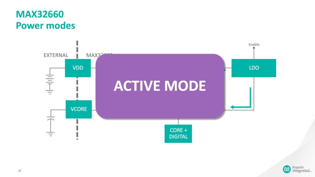
- A low-power microcontroller controls and coordinates the operation of the other components. Low-power modes let the microcontroller maximize battery life by spending most of its time in sleep mode and waking periodically to take measurements or respond to incoming data. The microcontroller also includes security features to guard against unauthorized access to patient or user data.
- The power block consists of voltage regulators, a voltage reference, protection circuitry, a battery, and battery-management circuitry. The voltage regulators can include both linear and switching topologies. If the battery is rechargeable, there is also a wired or wireless charger.
- A wired or wireless data port exchanges information with other devices. Depending on the application, common interfaces include USB, Wi-Fi (IEEE 802.11), and Bluetooth low energy (BLE).
- Finally, there is a human-to-machine interface (HMI) to show the results and accept user input. The HMI typically includes a display, switches, a loudspeaker, and perhaps a microphone, with accompanying interface components such as display drivers, ADCs, and digital-to-analog converters (DACs).
The similarities don’t end with the hardware: they also have many software elements in common. For example, data security is critical to both health and fitness applications. Encryption and authentication are a key component in most designs. If the product is used in a medical setting, regulations such as the Health Insurance Portability and Accountability Act (HIPAA) may require security to be designed in. Other common software elements include a BLE or USB stack, display drivers, or user-interface routines.
A ready-made development platform cuts time-to-market
Designing a wearable health or fitness product can be complex, yet designers may frequently be under enormous time-to-market pressure. Since many portable health and fitness products have similar requirements to the two discussed above, component vendors are helping cut development time by providing ready-made development platforms. These can form the basis for multiple health and fitness applications.
Maxim Integrated's MAXREFDES100# hSensor Platform, for example, includes all the hardware building blocks together on one pc board. It also has readily accessible hardware functionality with the ARM mbed hardware development kit (HDK).

Figure 4: The hSensor Platform helps designers quickly get started with a ready-made health and fitness platform. (Image source: Maxim Integrated)
The hSensor Platform includes an hSensor board, firmware with drivers, a graphical user interface (GUI), and a debugger board.
The firmware source code is available on Maxim’s website so that designers can load algorithms to adapt the platform to different use cases. Customers can download the firmware to optimize designs, enable faster evaluations, and significantly reduce time-to-market. The schematics, bill of materials (BOM), layout files, Gerber files, and software are also available online.
The components in the hSensor platform are designed for portable and wearable applications, with features to reduce overall power consumption (Figure 5). The board measures 25.4 mm x 30.5 mm, small enough to accommodate chest-based, arm-based, wrist-based, finger-based, and ear-based clinical or fitness applications.

Figure 5: The hSensor platform includes many common health and fitness building blocks. (Image source: Maxim Integrated)
Sensors and AFE circuitry
The platform includes sensors for many of the common health and fitness functions. It can measure skin temperature and heart rate, and supports a variety of biopotential measurements such as ECG, electromyography (EMG), and electroencephalography (EEG). For fitness band applications, a combination accelerometer/gyroscope senses motion and rotation; the platform also includes a barometric pressure sensor.
Several specialized devices support the biological functions. The MAX30101 optical sensor, for example, integrates optical and electrical functions to make a high-sensitivity pulse oximeter and heart rate sensor (Figure 6).

Figure 6: The MAX30101 is a single-chip pulse oximetry sensor that includes both optical and electronic elements. (Image source: Maxim Integrated)
The MAX30101 combines red, green, and IR LEDs, a photo diode, and AFE circuitry – such as an 18-bit delta-sigma ADC – with ambient light cancelation. Communication is provided by the industry standard I2C interface. A proximity function reduces power consumption when the user’s finger is not near the sensor.
The MAX30205 clinical-grade temperature sensor provides 0.1°C accuracy with 16-bit resolution. It is optimized for use in wearable devices with low-voltage (2.7 V – 3.3 V) and low-current (600 μA) operation. The part includes an overtemperature alarm and communicates via an I2C port. When soldered on the production pc-board, its accuracy meets the clinical thermometry specification of ASTM E1112.
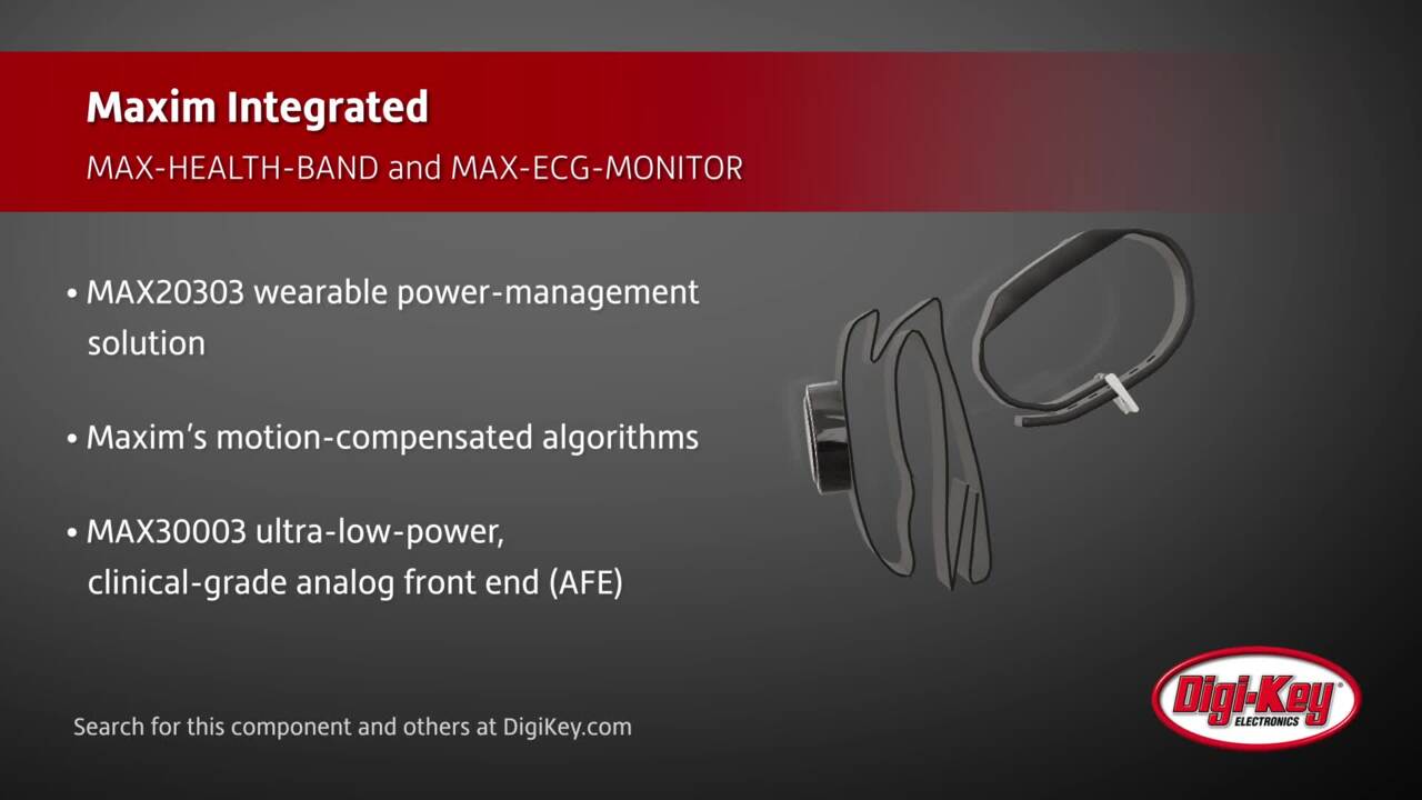
The MAX30003 single-channel integrated biopotential AFE provides the interface for ECG applications. The signal chain includes an input multiplexer and an instrumentation amplifier, followed by a low-pass filter with a selectable cutoff frequency and a PGA.
Like other hSensor devices, the part helps prolong battery life, with low 85 μW power consumption at 1.1 V operation. It also includes a function to keep the part in deep-sleep mode until it detects a valid ECG lead. To reduce the power consumption further, a configurable interrupt can wake up the microcontroller only on every heartbeat.
Microcontroller
The controller is an ultra-low power microcontroller based around the 32-bit ARM® Cortex®-M4F core plus a floating-point controller. Like other hSensor components, the microcontroller is optimized for wearables, with four flexible power modes and firmware controlled power gating to minimize power consumption. The part includes a four-input, 10-bit ADC with a selectable voltage reference, and communication options that include SPI, UART, and I2C serial interfaces, as well as an integrated USB 2.0 transceiver and a 1-Wire master module.
Power block
The MAX14720 forms the heart of the power-management block. The device is designed for space-constrained, battery-powered applications and integrates a power switch, a linear regulator, a buck regulator, and a buck-boost regulator. An external push button controls the MAX14720 power sequencing: a three second push turns on the PMIC, then twenty seconds later, turns it off.
Data communications
The hSensor platform includes both wired and wireless communications ports. The microcontroller provides USB 2.0 from a reversible USB Type-C connector to minimize the board size. Wireless BLE communication is courtesy of EM Microelectronics’ fully integrated single-chip controller, enabling the hSensor platform to act as either a BLE master or slave.
Software support
Software support includes both PC and Android. The PC application provides a GUI allowing the use of USB to configure the system and read sensor data. The Android application provides BLE capability.
Developers can customize the platform operation using the ARM mbed development environment. The reference design includes the MAXREFDES100HDK# programming adapter that provides driverless drag-and-drop programming for firmware updates, plus a virtual UART interface and a debugger that is compatible with ARM’s CMSIS-DAP interface firmware.
The firmware uses an interrupt-driven model shown in Figure 7. After power up, the microcontroller configures the power management device and sensors to their default settings. It then waits for remote procedure calls (RPCs) from the GUI or Android application.

Figure 7: The MAXREFDES100#’s firmware flowchart (version 10) is based on an interrupt-driven model. (Image source: Maxim Integrated)
Conclusion
Wearable products for the health or fitness markets must satisfy stringent performance requirements, consume minimum power, and fit into an extremely small package. The design must combine specialized sensors, precision analog circuitry, digital control, and wired or wireless communication.
For health sensor applications, a working hardware and firmware platform allows designers to quickly validate concepts, or use the platform’s existing features as a basis for new designs.
Maxim’s MAXREFDES100# reference design provides such a platform. It is optimized for this application, with designed and tested blocks to simplify the design and shorten time to market. It includes the hSensor Platform with multiple health related sensors and an industry standard ARM core microcontroller, together with a robust software ecosystem complete with downloadable source code.
Using these components, a designer can quickly configure the base design, concentrate on the features that differentiate the product, and drastically reduce time-to-market by several months. In the fast-paced health and fitness wearables market, that can be the difference between success and failure.
免责声明:各个作者和/或论坛参与者在本网站发表的观点、看法和意见不代表 DigiKey 的观点、看法和意见,也不代表 DigiKey 官方政策。


 中国
中国