Developing Modern Telecom Applications
投稿人:Convergence Promotions LLC
2013-01-17
Where would we be without modern day communications? Probably back in the grey ages – not quite the dark ages, but pretty close. Communications, modern electronics, and telecom equipment are the backbone of our civilized connectivity. We have cell towers, satellite phones, Wi-Fi zones, legacy POTS lines, and emerging standards that will usher in even more capabilities and higher bandwidths.
At every point, in this ambiguous cloud of connectivity, is equipment that an engineer has designed, debugged, tested, and moved into the manufacturing environment. The modern day worldwide infrastructure includes some of the oldest and some of the newest technologies that need to play nicely together. Different communications standards and techniques need to seamlessly integrate in order to make any communication network viable.
That is where development systems and reference designs come into play. It is the device manufacturers who integrate huge chunks of the necessary technology into small chips, devices, and modules. To facilitate the use of their products, the development kits often do much of the design work for us and provide a high-level starting point for any design.
This article discusses some of the readily available telecom development kits to help us with our designs. It also discusses some of the parts the development systems support. All parts, tools, data sheets, reference designs, and training information referenced here are available online on the DigiKey website.
Have I reached the party to whom I am speaking?
The legacy plain old telephone systems (POTS) are the most successful deployment of mass communications, historically speaking. For more than 50 years, POTS systems have delivered reliable, quality service to households around the world.
While cellular and IP-based telephones are catching up and even surpassing POTS systems in developing countries, do not dismiss POTS technology. IP-based telephone systems, as well as cable modem, DSL, and fiber optic systems, will still provide a POTS interface. Most households are already wired for this and it makes converting from legacy POTS systems to IP systems easier without any infrastructure modifications.
Underlying this technology are central office (CO) and user endpoint interface circuits. The user’s endpoint is called a subscriber line interface circuit (SLIC) and a central office interface device is called a data access arrangement (DAA). These two types of circuits completely implement the communications link including the signaling (ring, ring detect, on-hook and off-hook detect, busy detect and indication, and bi-directional audio) over a two-wire interface.
Both of these functions can be implemented discretely, but most will choose an integrated solution to save time and PCB space. For example, if you are designing a cable modem you will have your interface to the cable company on one side, with Ethernet ports, possibly a USB port or two, power supplies, battery backups (required if telephony is to be provided), and a DAA circuit like the CP Clare (now IXYS Corporation) LiteLink III CPC5622ATR phone line interface IC (see Figure 1). This part mimics the legacy telephone company to allow all the house phones, answering machines, faxes, and modems to connect. Running on 3.3 or 5 volts, this DAA incorporates caller ID signaling, ring voltage and waveform generation, line voltages for on-hook and off-hook power and detection for voice and data in a 32-pin SOIC package.

Even though POTS technology is well defined and understood, designers have pressures to prove feasibility, prototype quickly, and be able to quickly demonstrate and test their designs. To aid in this effort IXYS makes available the CPC5622-EVAL-600R development module that not only demonstrates the CPC5622 operations but also implements it in a SIP-pluggable module that can easily be incorporated into your prototype (see Figure 2).

This evaluation/development board lets you adjust the AC and DC terminations through the use of a programmable driver, allowing customization for the slight variations that exist from country to country. You can also customize the caller ID signal gain as well as the ring-detect signal strength. These parts also support enhanced pulse dialing modes as well as ground-start supervisory circuitry. Also included are complete reference designs to help speed the implementation from prototype to board layout.
Press “1” to speak to a human (good luck)
Dual-tone multi-frequency signaling (DTMF) is an integral part of modern day telephony design. It has made dialing faster and more reliable, and has made it possible for equipment like answering machines to respond remotely to our requests, enabling us to play messages and re-record greetings from anywhere in the world.
Unfortunately DTMF also enables non-human automated systems to drive us crazy when trying to get customer assistance, but we have to take the bad with the good. In any case, DTMF generation is a vital part of any end-user equipment, and DTMF detection is a vital part of any CO equipment or devices that need to imitate a central office.
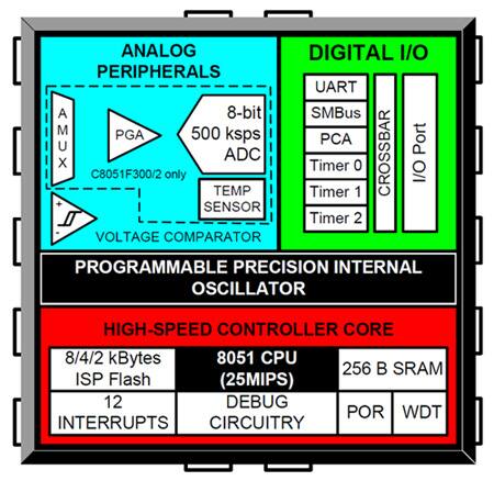
Fortunately, there are chips and development kits to aid in this area of design, as well. For example, Silicon Labs’ C8051F002-GQ is an integrated, 8-bit microcontroller along with analog blocks which can perform mixed-signal functions like DTMF. DTMF functions are basically a mixed-signal technology since the actual DTMF tones are analog AC waveforms, while the actual numerical codes are digital binary or hexadecimal numeric values. As a result, DTMF encoders and decoders are mixed-signal devices that can either be discrete encoders and decoders or bundled with a programmable microcontroller as is this part.
The C8051F002-GQ features a popular 25 MIPS 8051 microcontroller core with integrated 8 Kbytes of Flash. The 2.7 to 3.6 volt parts are 5 volt tolerant and range from small 11-pin QFN or 14-pin SOIC packages up to 48-pin TQFP packages which have more I/O and Flash (up to 32 K). This means that if you are good with tight coding, you can make this part function as the heart of a DTMF processing system such as alarm monitors, remote controls, and repeater switches.
These parts are ideally suited to implement a DTMF communications scheme with built-in encoder and decoder functionality along with a UART, programmable gain amplifier, timers, counters, and I2C ports (see Figure 3).

A particularly nice feature is the ability to switch clock sources on the fly between a 25 MHz crystal and an RC oscillator. This way, if the UART is needed, the higher frequency crystal can assure reliable timing for communications while the RC oscillator can be kicked in for lower power and standby modes.
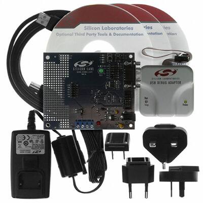
Since the C8051F002-GQ is more than just a mixed-signal encoder/decoder chip, Silicon Labs provides a development environment for this part that supports the DTMF functionality. Their C8051F300DK development kit (see Figure 4) supports code development for the in-system programmable internal 8051 microcontroller as well as providing a complete reference design and flexible board that contains DTMF generator, decoder, beeper, RS-232 port, and numeric display.

The DTMF detector can accept inputs from an external jack or a wave file, or it can be looped from the DTMF generator. This lets the designer test different stages of functionality using the same board. Typically DTMF systems are interactive, meaning the microcontroller will need to implement a complete menu system that responds to user commands and requests. This part can be used stand-alone for simple applications that can fit into the limited 8 Kbytes of Flash, or it can be programmed to become a peripheral to a more powerful embedded microprocessor or microcontroller.
Silicon Labs makes available several prototyping and evaluation aids for these parts including several USB-based plug-in development tools such as TOOLSTICKSK and TOOLSTICK-EK units for fast code development and test. A training module is also available that provides a good overview of serial communication technologies using these parts and the development tools.
Embedding modems into your design
Not every telecom design needs humans in the loop. Data-based systems for remote reboot, telemetry, distributed sensors, and alarms can be completely automated to use telecom backbones to report in or to control machines remotely. In these cases, embedded modems allow equipment designers to establish communications and transfer data with whatever protocols or data exchange structures they want to create.
Fortunately, we have choices and integrated solutions for these designs, as well as tools to help us develop, debug, and test our creations. At a higher level of integration and functionality are embedded and modular modem solutions that provide seamless and transparent machine to machine connectivity.
Why higher level you may ask? Because the embedded modems not only house the modem MODulator and DEModulator functions, they also house a form of subscriber line interface like the circuits mentioned above. They need to extract the audio from the telephone lines, send their signal out, detect ring and off-hook, and possibly incorporate caller ID and DTMF dialing.
Since several different modem standards exist, there are several different options from which to choose. Some standards are country- or region-specific, and others use older data rates and formats.
Keep in mind that though this is an older technology, a lot of legacy systems are in place, especially at remote sites, that gather anything from seismographic data to weather and tectonic plate shifting. This is a reliable and proven technology that is not going away, and new designs based on it are viable, especially when the need exists to connect to the millions of deployed data nodes already in the field. This is why modern-day integrated modem modules will incorporate most of the older standards. For example, Multi-Tech’s MT5656RJ-L-92.R3 is an RJ-11-based surface-mount integrated module that supports up to 56 Kbaud data rate and all the popular backward-compatible standards such as V.21, V.22, V.23, V.29, V.32, V.34, V.90, V.92, Bell 103, and Bell 212A.
Interfacing with these modules is fairly straightforward through the use of UART signaling and AT-style command structures. However, we often have to design systems that will be deployed in different parts of the world that employ different standards. To help with the development of flexible, multi-standard designs, Multi-Tech makes available some development systems that can be used to evaluate, develop, test, and exercise the designs that house their embedded modem modules. For example, the MTRJ-DK and the MTSMI-UDK are development systems that provide support for any of the individual or multi-format RJ-11-based integrated modem modules (see Figure 5).

An important point is that not every modem connects to a telephone line. Wired point-to-point modems have their place in this world too. Take for example the highway-addressable receivers and transmitters (HART) technology in use by industrial automation. These are slow, long-distance data transport standards that must be able to interoperate with other manufacturer’s equipment. As a result, chip makers support these standards with devices and development kits.
An example of this is with the Analog Devices AD5700-1BCPZ-R5, a single-chip FSK modem for HART applications. Based on 1200 Hz and 2200 Hz frequency shift modulation, these parts include ESD protection and filtering and are suitable for intrinsically safe design applications.
Other nice features are the very low power (115 µAmps in receive mode), the ability to operate from a 2 to 5.5 volt power supply, and the ability to accept signals as low as 1.71 volts. The UART interface does not require RS-232 level shifters and the internal oscillator is rated with 0.5 percent accuracy.
Micro DTMF, and speech in one part
With flexible peripherals and a sufficiently powerful processor, even general-purpose microcontrollers can tackle some fairly high-end tasks. However, when a part is designed with a specific class of functionality in mind, it is usually the best fit.
An interesting blend of technology comes from Atmel with its U4091 family of audio processors, suitable for implementing modem and DTMF and speech functionality. An Atmel training module can introduce you to the processor family and the DEMOBOARD-U4091BM is the way to get your applications up and running quickly.
The U4091 family incorporates DTMF, speech processing, voice switching, and tone generation for acknowledgement and prompting. It can be programmed with its own functionality and can communicate with other CPUs through serial buses.
You light up my life
Some of the most useful development systems for telecom are fiber-optic modules. These high-speed modules require good PCB layout and often also high speed processors and interface elements. As a result, small boards that are part of a development environment can provide a reference design on which to base and against which to compare your implementation. Often suggested layouts and even completed reference designs (including Gerber files) are available from different manufacturers that can speed time to market. These development modules are a fast and effective way of testing your initial design before committing to high-cost production prototypes.
An example of this type of fiber optic development system comes from Finisar with the FDB-1018 and the FDB-1022 development systems for small form factor pluggable (SFP) optical transceivers and extended-reach 10 Gbit/sec XFP optical transceivers, respectively. The FDB-1018 supports 125 Mbit/sec and 4.25 Gbit/sec data rates, and the FDB-1022 supports 10 Gbit/sec data rates.
Finisar’s family of integrated fiber optic modules service the telecom markets with support for telecom standards like SONET OC-3, OC-12, and OC-48 as well as 1 Gbit/sec and 10 Gbit/sec Ethernet. This is helpful since many of the older ATMs, inverse MUXes, and T3/E3/J3 standards are giving way to TCP/IP-based implementations; especially as quality of service issues are being resolved.
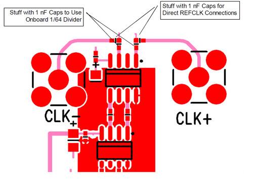
Evaluation boards such as the ones from Finisar not only serve as vehicles for testing connectivity with your prototypes and designs, but they also provide reference schematics and detailed PCB layouts, which are increasingly important at higher data rates. For example, the 10 Gbit/sec reference design not only includes the PCB patterns, but also the placements and orientations of the bypass and decoupling elements (see Figure 6). This is important since at higher speeds, signal paths can become antennas instead of transmission lines depending on how well impedances match.

Don’t forget to take advantage of documentation as well as factory experts and FAEs. They can hand hold, especially with the newer technologies. The expertise and availability of demo, development, and evaluation boards coupled with the one-stop source of data sheets, training, and parts from DigiKey all form a multi-tiered support structure to help ensure that your designs work as expected, are on time, and are under budget.

免责声明:各个作者和/或论坛参与者在本网站发表的观点、看法和意见不代表 DigiKey 的观点、看法和意见,也不代表 DigiKey 官方政策。


 中国
中国