Buck-Boost Design Solutions
投稿人:电子产品
2012-04-24
Fundamentally, there are two common topologies for changing a source voltage to that required by a load. Buck regulation steps down the input voltage, while boost is a voltage step-up topology. Nevertheless, many mobile or battery-powered applications have a need for a third option, the buck-boost. In this case, the input voltage can range from above to below the voltage required by the output load.
A good example representing such a need is a mobile device powered by a lithium-ion battery whose voltage can vary from less than 3 V to 4 V, while operating voltage for most of the ICs in the circuitry of the device is 3.3 V. Some mobile applications require even lower voltages and, therefore, must operate from two alkaline or nickel-metal-hydride (NiMH) cells. Just as with Li-ion, the voltage delivered by alkaline and NiMH cells can also vary ±10 percent. What is more, the load in such systems can change rapidly from sleep/idle mode to active mode, at which point the specified regulated voltage demanded by the circuit must be delivered.
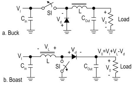
Designing a buck-boost converter becomes challenging when the circuit must regulate input voltages that are very close to the specified output voltage. There are a number of circuits that have been developed over the years, sharing a number of common elements with buck and boost topologies, as depicted in Figure 1.[1]

While the inverting buck-boost is the simplest of the circuits, providing an output whose polarity is opposite to the input, the non-inverting topology can be implemented using a charge pump, flyback or single-ended, primary inductor coupled (SEPIC) topologies. However, the downside of these circuits is that they may have limited performance.
For instance, the charge pump provides a simple, low-cost solution but is generally limited to a few hundred milliamperes (mA). Flyback requires a costly coupled inductor specifically wound for the application and is inherently noisy. Likewise, SEPIC offers lower efficiency. Although efficiency of the SEPIC converters has improved lately with the development of monolithic capacitors, it still suffers lower efficiency due to losses in the inductor. Plus, it costs more and its size is not attractive for mobile applications.
H-bridge buck-boost
Another option is the H-bridge buck-boost circuit1. In essence, it is simply a buck and a boost sharing one inductor as shown in Figure 2. In this solution, the diode for the buck section has been replaced with a synchronous FET (S2) for improved efficiency. FET (S4) replaces the diode in the boost section. Because these FETs can be easily integrated, the H-bridge buck-boost solution can be quite small and simple to design with, requiring just two external, off-the-shelf capacitors (Cin and COut) and the inductor.

Besides simplicity, the H-bridge also offers high efficiency, high load current capability, and good line transient response. Plus, it requires little quiescent current. On the other hand, it must possess the ability to decide whether to operate in buck, boost, or buck-boost mode. The transition point between these operating modes and the speed at which the device can transition can be critical to maintaining a regulated output voltage.
To address such needs, suppliers such as Intersil have exploited H-bridge architecture to develop integrated buck-boost regulators like the ISL9110 and ISL9112 that represent state-of-the art solutions. ISL9110 and ISL9112 are both highly-integrated buck-boost switching regulators that accept input voltages either above or below the regulated output voltage. They also are designed to automatically transition between operating modes without significant output disturbance. Both the regulators are capable of delivering up to 1.2 A output current with excellent efficiency due to their fully synchronous four-switch architecture. No-load quiescent current is only 35 μA. Designed for standalone applications, ISL9110 supports 3.3 and 5 V fixed-output voltages or variable output voltages with an external resistor divider. In fact, output voltages as low as 1 V, or as high as 5.2 V, can be realized using an external resistor divider.
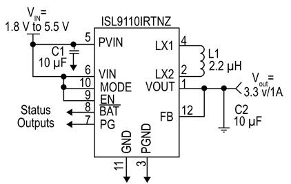
A typical application circuit using ISL9110 for a 3.3 V/1 A output with 1.8 to 5.5 V input range is shown in Figure 3. Note that as shown, only a few external passives are needed to complete this design. Also, the 2.5 MHz switching frequency further reduces the size of external components.

The efficiency curve plotted in Figure 4 shows the design is optimized to deliver high efficiency even under light-load conditions. Typical power conversion efficiency under high-load conditions is over 90 percent.

Unlike ISL9110, the ISL9112 features an I2C interface for programmability of the output voltage on the fly. It also controls the rate of change of the output voltage transition. With a programmable output voltage range of 1.9 to 5 V, the ISL9112 is ideal for applications requiring dynamically changing supply voltages. A programmable slew rate can be selected to provide smooth transitions between output voltage settings.
Texas Instruments is another vendor serving this space . Like Intersil, TI's single-inductor buck-boost converters integrate four power MOSFETs on-chip to save space and seamlessly transition between modes of operation. TPS63060 and 61, for example, provide a power supply solution for products powered by three-cell up to six-cell alkaline, NiCd, or NiMH batteries, or a one-cell or dual-cell Li-ion or Li-polymer battery. The input voltage range for this part is 2.5 to 12 V with an output voltage range of 2.5 to 8 V. Output currents can go as high as 2 A while using a dual-cell Li-ion or Li-polymer battery and discharge it down to 5 V or lower. The buck-boost is based on a fixed frequency, pulse-width-modulation (PWM) controller using synchronous rectification to obtain maximum efficiency. It comes in a 10-pin SON PowerPAD package measuring 3 × 3 mm.
For very wide input, TI offers its TPS55065, a switch-mode buck-boost regulator with integrated switches for voltage-mode control. With few external passive components, the converter regulates the output to 5 V ±3 percent from a wide input voltage range of 1.5 V to 40 V. It can deliver output current up to 500 mA.
Linear Technology’s entry for very wide input and output voltages is its LTM4609, a high efficiency (up to 98 percent) switch- mode buck-boost DC/DC converter. The switching controller, power FETs, and support components are included in a single LGA package. It operates over an input voltage range of 4.5 to 36 V, and supports an output voltage range of 0.8 V to 34 V, set by a resistor. This high efficiency μModule design delivers up to 4 A continuous current in boost mode (10 A in buck mode). Only an inductor, sense resistor, bulk input, and output capacitors are needed to complete the design.
Summary
The market for handheld mobile devices is demanding higher application performance and higher data transfer rates in the smallest form factors possible. To meet this demand, manufacturers are aggressively trying to miniaturize components and reduce board space without impacting performance. Buck-Boost regulators accept input voltages either above or below the regulated output voltage. This is needed because in mobile handsets, for instance, source voltage can vary from less than 3 to 4 V, while operating voltage for most of the ICs in the circuitry of the device is 3.3 V. This article has examined several buck-boost topology solutions and presented representative products from manufacturers such as Intersil, Linear Technology, and Texas Instruments. More information on these parts can be obtained by using the links provided to access product information pages on the DigiKey website.
Reference:
- Basics of Design: H-Bridge Buck-Boost Converters by Larry Bradley and Sameer Dash, Intersil Corp.
免责声明:各个作者和/或论坛参与者在本网站发表的观点、看法和意见不代表 DigiKey 的观点、看法和意见,也不代表 DigiKey 官方政策。


 中国
中国