Antenna Matching Within an Enclosure: Theory and Principle
投稿人:DigiKey
2012-12-13
Developing a wireless product can be a daunting task. There are many pitfalls, traps, and common mistakes people fall into during design and development. It is very common to save the implementation of the antenna for last. The fact of the matter is that the antenna makes your product wireless. It is the most critical component that launches your signal into space. Often little consideration is given to the antenna location and how the object nearby can affect it. This can be devastating not only to a product’s performance, but also to schedule and cost.
An antenna is a function of its environment. Whether it’s sitting on a desk, on a manufacturer’s development board, or in a product, all three scenarios result in different performance. Unlike most components in a design that can be dropped in with an expected effect on the circuit, an antenna is affected by everything around it. The radiated electromagnetic fields from an antenna interact with nearby materials, and can change its frequency of operation. The antenna must be placed in its final environment and impedance matched so that it operates in the desired frequency band. A poorly matched antenna can degrade your link budget by 10-30 dB and severely reduce range. All antennas, whether they are off-the-shelf or designed in a lab, may require matching.
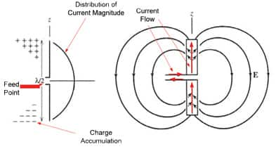
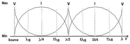
To understand why an antenna is affected by objects near it, how an antenna radiates must be reviewed. First, forget about what is happening to the antenna or what is nearby. What is important is the input impedance to the antenna. Examining the dipole in Figure 1, when a potential is applied to the antenna inputs, there is opposite charge buildup on the ends. Essentially the dipole ends can be viewed as open circuits, with a high voltage and no current. Due to the charge buildup at either end of the dipole, current begins to flow. As you move from the end of the dipole inwards towards the feed point, the voltage falls and the current rises. At the feed point, the current reaches its peak along with some now reduced voltage. The ratio between the voltage and current at the feed point is the input impedance to the antenna. This is the impedance that drives the antenna performance. Additionally, since there is current flow on the antenna, electromagnetic fields are radiating.

The antenna impedance acts as a load impedance for the transmission line that carries the signal to the antenna. The impedance of the antenna determines the voltage and current along the transmission line as well as their phase relationship. On the transmission line, there is a Standing Wave Ratio (also known as VSWR). This ratio measures the amount of standing wave versus traveling wave. Roughly speaking, a VSWR = 1 means a pure traveling wave, and a VSWR = ∞ means a pure standing wave. A very low VSWR is desirable because it indicates that most of the energy is being delivered to the antenna. A high VSWR means most of the energy is being reflected back onto the transmission line and is not being radiated. When the antenna is matched at the transmission line terminals, there is a low VSWR. Energy that is not delivered and instead reflected back at the antenna input can affect the RF circuitry, as it must be dissipated elsewhere.

The antenna impedance changes with frequency because the current distribution is directly related to the wavelength. The current and voltage on the dipole form a sinusoidal distribution, so as the distance from the end of the dipole to the feed point varies by fractions of a wavelength, so does the impedance.


When the antenna is placed in an enclosure, the electromagnetic fields interact with the surrounding materials. As a result, the fields develop differently than they would in free space. This interaction ultimately changes the current distribution on the antenna, and consequently its impedance. This is why an antenna must be tuned in its final enclosure. The antenna impedance will shift depending on the proximity, electrical properties, and size of the surrounding materials. An antenna design can be ruined if it is not tuned properly during implementation.
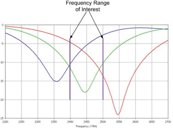
Antennas can be tuned one of two ways, either by adjusting the dimensions or with a matching network typically consisting of discrete components. Typically, changing physical dimensions is not an option, so a discrete network is placed just before the antenna input. The challenge with tuning an antenna is that its impedance is affected by nearby materials. If you tune the antenna to 2.4 GHz on your bench and then place it in an enclosure, the tuned frequency will shift. Figure 3 below demonstrates this effect. The red line is the antenna in free space, unmatched. The green line represents the same antenna now matched in free space. The blue line is the final antenna response when placed in the enclosure. Since the antenna was not tuned in the enclosure, the impedance is not matched to the 50 Ohm PCB trace line over the frequency of interest. The antenna must be tuned in the enclosure to allow for the changes in impedance to be accounted for. This is true for all antennas, including chip and other pre-packaged antennas.

Further complicating the matter, no two materials affect the antenna the same. For example, a common mistake is to use a prototype enclosure that is similar in size and shape but not made of the same production quality material. Even by changing the PCB material on which a trace antenna is printed can cause the impedance match to change. The tuning of the antenna must always be rechecked if anything in the enclosure has changed, even objects several centimeters away can have an impact.
When deciding on a location for the antenna in your product, consider the following questions:
- What is the enclosure made out of?
- What will be near the antenna?
- Is there metal nearby?
- How will the device be used?
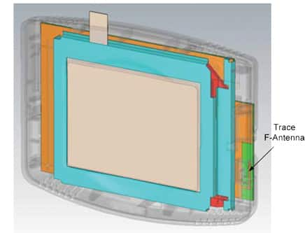
When it comes to tuning an antenna for its enclosure, there are many considerations. The process of tuning the antenna is difficult and time consuming. In many cases, there are other PCBs, housing materials, batteries, display screens, metal brackets, and various other harmful objects nearby. All of these affect the tuning and must be present. The antenna location should be one of the first things considered when developing a new product; but it is often the last component to be finalized.

The most effective method to anticipate antenna tuning and radiation problems is to use simulation software to evaluate and predict the effects of an enclosure. An antenna designer must identify the materials in the product, define their electrical properties, and understand how the antenna will interact with them. A well designed and simulated antenna will usually require no matching network; however it will only be tuned correctly for the exact product for which it was designed.

免责声明:各个作者和/或论坛参与者在本网站发表的观点、看法和意见不代表 DigiKey 的观点、看法和意见,也不代表 DigiKey 官方政策。


 中国
中国