An Engineer's Guide to Power Inverters for Solar Energy Harvesting
投稿人:电子产品
2012-04-04
Home energy systems based on renewable sources, such as solar and wind power, are becoming more popular among consumers and will gain increasing support from governmental bodies.
In this article, the power inverter will be discussed in the context of solar energy, especially as it relates to the latest, low power microinverter architectures that make the most sense in converting a photovoltaic (PV) panel’s DC output to an AC signal for residential use.
Microinverters are installed on each individual PV panel and typically handle 300 W. Microinverters provide the benefit of scalability for those who want to start small, yet have full DC/AC conversion with maximum power point tracking (MPPT). Many people want to put their excess power back onto the power grid, which will speed up the return on investment (ROI) time and ultimately could lead to freedom from grid reliance. The technology that will enable ubiquitous architectures like this on our roof is getting closer.
Microinverters maximize the power collected from every panel and are not affected by a particular solar panel performing poorly. String inverters will be restricted to the actual power produced by the least effective solar panel within a string. If a single panel is dusty, defective, aligned differently, or a different model of solar panel, etc., it drags down an entire string. A microinverter’s individualized solar panel harvest will supply somewhere between a 5 percent and 25 percent increase in electricity output when compared to a string inverter configuration.
Solid-state inverters have been shown to be the enabling technology for putting PV systems onto the grid. A cost reduction per inverter Watt is, therefore, important to make PV-generated power more attractive (Figure 1).
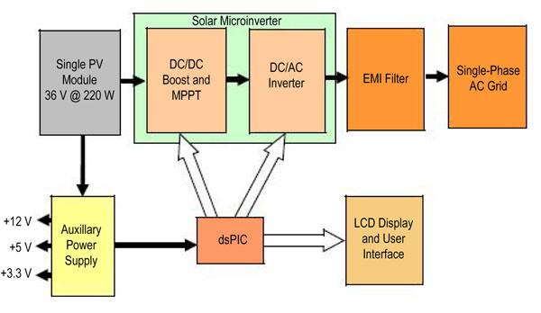
Let’s follow the PV signal from DC source to AC power output and examine the key component blocks of the system.
General architecture of the inverter
There are essentially three types of PV inverter architectures (Figure 2). Figure 2a shows a typical centralized inverter that handles all tasks by itself such as MPPT (usually by the microcontroller), grid current control, and voltage amplification, if needed, since the low voltages out of the PV source cannot easily be inverted to grid voltage levels efficiently.
Figure 2b is a dual-stage inverter. The DC/DC performs the MPPT and voltage amplification if needed. Depending upon the control of the DC/AC inverter, the output from the DC/DC converters is either a pure DC voltage (and the DC/DC converter will only handle the nominal power), or the output current of the DC/DC converter is modulated to follow a rectified sine wave (the DC/DC converter will handle a peak power of twice the nominal power). The DC/AC inverter in the former solution is controlling the grid current by means of pulse-width modulation (PWM) or “bang-bang” operation. In the latter, the DC/AC inverter is switching at line frequency, “unfolding” the rectified current to a full-wave sine, and the DC/DC converter takes care of the current control. A high efficiency can be reached for the latter solution if the nominal power is low. On the other hand, it is advisable to operate the grid-connected inverter in PWM mode if the nominal power is high, which in our case will usually not be the issue.
Figure 2c is the solution for the multistring inverter. The only task for each DC/DC converter is MPPT and perhaps voltage amplification. The DC/DC converters are connected to the DC link of a common DC/AC inverter, which takes care of the grid current control. This is beneficial since better control of each PV module/string is achieved.

DC/DC boost converter
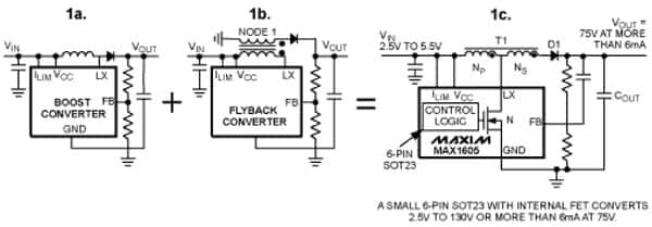
We will first discuss the DC/DC boost converter (or buck/boost in some cases) which is shown in Figure 1. The DC/DC conversion raises or lowers the incoming PV voltage, adjusting its output for greatest efficiency (MPPT) to the DC/AC inverter stage. A schematic containing discrete design components is shown in Figure 3 using Maxim’s MAX1605, but even a power module may be used if the designer wishes.
The Texas Instruments/National Semiconductor SM72442 is a more integrated solution for this front-end stage. The SM72442 is a programmable MPPT controller capable of controlling four pulse-width modulation (PWM) gate drive signals for a four-switch buck/boost converter.
DC/AC inverter
The next stage is the actual power inverter itself, being driven by a DSP or microcontroller with multiple PWM outputs to drive the power IGBTs or the MOSFETs. Depending on the electrical isolation between the PV panels and utility grid, the inverter can be isolated or nonisolated. This galvanic isolation is usually realized by the means of a transformer, which has major influence on a grid-connected PV systems’ DC/AC efficiency.
Most single-phase H-bridge inverters use unipolar PWM in order to improve the injected current quality of the inverter, which is done by modulating the output voltage to have three levels with twice the switching frequency. Moreover, this type of modulation reduces the stress on the output filter and decreases the losses in the inverter (Figure 4).
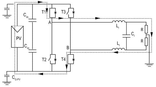
PV inverter systems can be improved, in terms of efficiency, using transformerless topologies, but new problems related to leakage current need to be dealt with. Care must be taken regarding the leakage current phenomenon that can damage solar panels and pose safety problems. In a transformerless PV system using this type of topology and modulation (Figure 4), the high-frequency common-mode voltage will lead to very high leakage ground current, making it unsafe, therefore not usable, for transformerless PV applications. It is best to use this technique in a transformer-based inverter design.
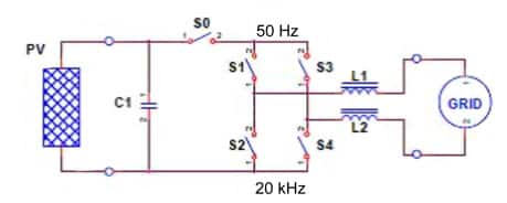
Another patented inverter topology is again an H-bridge hybrid. SMA Solar calls it the H5 topology. As detailed in Figure 5, it is made up of a standard H-bridge topology with an added fifth switch on the DC side (So). Using this circuit configuration, maximum conversion efficiencies of up to 98 percent have been reported, depending on the input voltage. The H-bridge works by asymmetric unipolar modulation. The high side of the asymmetric H-bridge should be driven by a 50 Hz (Europe) or 60 Hz (USA) half-wave dependent upon the polarity of the mains, while the opposite low side is PWM modulated to form the mains sinusoidal shape. There will be some heavy filtering done here, as seen in Figure 5, with the inductors as part of an AC output filter, including EMI suppression capacitors, to give a smooth AC that can be accepted on the grid or used in the home.
There are also many other, more complicated topologies that are a combination of multiple boost or buck-boost single-stage inverters.²
Microcontroller or DSP
The microcontroller or DSP can be such devices as Texas Instruments’ TMS320F2812, Freescale’s 56F8036 or Microchip’s dsPIC DSPIC33FJ16GS504. Figure 6 shows the microcontroller PWM control of the bridge as well as the on-board analog to digital converter (ADC) to monitor critical parameters of the system.
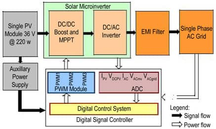
Residential-scale grid-tie systems are the most common systems today. They typically provide 3 to 10 kW of output power and are not normally accompanied by a battery backup. Output AC power must be synchronized in phase, frequency, and voltage to the grid and have a low total harmonic distortion. String inverters, which control one or more strings of individual PV modules, are the most common types of inverters used for residential applications. The Freescale 56F83xx series of digital signal controllers (DSCs) provide single-chip control solutions for both MPPT and DC/AC conversion. See Figure 7 for a more detailed view of the typical inner workings of the DC/DC booster, DC/AC inverter, and DSC/microcontroller.

Isolation
Now let’s look at the isolation in an inverter design. Regardless if the inverter is transformer-based or transformerless, some sort of isolation will be needed (Fig. 8).

The system controller operates in a different voltage domain than the elements it controls. The power sources operate in the tens of volts and the DC Link at hundreds of volts, but the system controller’s logic circuits typically operate around 3 to 5 V. To minimize the possibility of damage to the controller in the event of a fault condition, there must be some type of isolation between the power and logic voltage domains. Such isolation not only serves to protect the controller logic from the high DC Link voltages, it helps protect the user, who typically interacts with the system through the controller’s interface.
Optical couplers from Avago Technologies offer reinforced galvanic isolation that increases safety and system reliability. Devices such as Avago’s HCPL-316J are gate drive opto-couplers with integrated protection features that isolate the MOSFETs or IGBTs in the H-bridge.
EMI Filter—DC side
Schaffner makes an FN2200 DC EMI/EMC filter that:
- Reduces conducted EMI towards the PV panel
- Decouples the PV panel and inverter
- Prevents premature panel ageing due to high frequency leakage currents
- Prevents radiation from the PV panel (EN standards in consideration)
- Is often used with transformerless inverters
The Vishay MKP339 X2 capacitors can also be used for the DC side for filtering of the DC/DC boost converter interference suppression.
EMI Filter—AC side
Schaffner makes an FN2030 AC EMI/EMC filter that:
- Reduces conducted EMI towards the grid
- Fulfills international EMC/RFI regulations
Summary
The latest designs of solar microinverters have heralded a new approach in making solar-powered systems more in tune with the energy efficiency goals of conscientious homeowners. The productivity of a solar-powered electricity system is greatly dependent on how the direct current produced from the panels is converted to alternating current. Traditional inverters have been found inefficient at the task due to some inherent design flaws.
When a system powered by a number of solar panels is connected to a single inverter, the efficiency levels that can be achieved are as good as those of the most inefficient panel in the array. Known as string inverters, these traditional devices come with very limited choices in power ratings. In effect, a homeowner is restricted to the power rating of the original panels in case they want to upgrade by adding on more modules. Conversely, microinverters do not have such restrictions.
For more information on the products mentioned, please use the links provided to access product pages on the Digi-Key website.
References
- A Review of Single-Phase Grid-Connected Inverters for Photovoltaic Modules by Soeren Baekhoej Kjaer, Member, IEEE, John K. Pedersen, Senior Member, IEEE, and Frede Blaabjerg, Fellow, IEEE; IEEE TRANSACTIONS ON INDUSTRY APPLICATIONS, VOL. 41, NO. 5, SEPTEMBER/OCTOBER 2005
- Analysis and Modeling of Transformerless Photovoltaic Inverter Systems by Tamás Kerekes, August 2009
免责声明:各个作者和/或论坛参与者在本网站发表的观点、看法和意见不代表 DigiKey 的观点、看法和意见,也不代表 DigiKey 官方政策。


 中国
中国