Power-over-Ethernet Adapts to Meet Higher Demand
投稿人:电子产品
2011-11-07
Being a resourceful species, it did not take long for engineers to realize that running two sets of cables–one for communications; the other for power–to remote devices such as security cameras was expensive and tedious. Fortuitously, the CAT 5 cable (and above) used for Ethernet networking is capable of carrying some tens of watts over long cable runs so it is perfect for doing both jobs. And so the concept of Power-over-Ethernet (PoE) was born.
This article provides an overview of PoE and its advantages, and includes a look at PoE+, a development of the technology that allows the cabling to carry higher loads. The article then looks at specialized parts from major suppliers that ease the job of setting up a PoE system.
The advantages of PoE
Perhaps the biggest benefit of PoE is its simplicity. Once it is installed for communication, standard Ethernet cable can be used for power as well. That saves on materials, labor, installation time, and ongoing maintenance costs. There is a need for PoE-compliant switches and power supplies, of course, but a range of vendors offer ready-to-fit products that are simple to install.
The centralized and flexible nature of PoE eliminates the need for each powered device on the network to have its own local power supply. That allows the devices to be placed anywhere and easily relocated later if required.
PoE offers further cost savings because it allows effective energy management capabilities via the PoE switches’ support of simple network management protocol (SNMP). This protocol gives the administrator the ability to monitor and manage power consumption from a remote location. For example, the administrator can decide if and when to put a device (or system) into low-power or sleep mode (for example, during off-peak hours like nights and weekends).
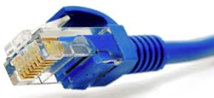
The technology’s power-carrying capacity means it can power equipment such as cameras, wireless LAN access points, remote Ethernet switches, embedded computers, thin clients, LCDs, and IP phones. PoE is superior to USB for these applications because it can carry more power over longer runs. Better yet, PoE uses a single, standard RJ45 connector in contrast to USB’s numerous connector types (Figure 1).

While PoE is primarily deployed where AC or USB power is not practical, it is also advantageous in many applications where the latter compete. These advantages include:
- Category 5 cable is cheaper than USB repeaters, and, unlike AC power, no adherence to building code requirements is required.
- Global organizations can deploy PoE without concern for local variance in AC power standards or outlets.
- Allowance for direct injection from standard 48 Vdc battery power arrays to cover for power outages.
- Allowance for symmetric distribution. Unlike USB and AC, power can be supplied at either end of the cable. This means the location of the power source can be determined after the cables are installed.¹
Adding to PoE
PoE is regulated by an IEEE standard, IEEE 802.3af, and is capable of supplying up to 15.4 W DC at the device (after taking into account losses in the cable run). This is a lot when compared to USB 3.0’s 900 mA. However, some devices that could benefit from PoE need even more power (for example, cameras with pan, tilt, and zoom capabilities).
So now, an enhancement to PoE, called PoE+ has made its debut. PoE+ is covered by another IEEE standard, this time IEEE 802.3at, and can supply up to 25.5 W DC to the connected device. PoE+ power sourcing equipment provides 50 to 57 Vdc compared to 44 to 57 Vdc for PoE. Current for PoE+ is increased to 600 mA compared to the earlier technology’s 350 mA.
The IEEE standard for PoE+ states that it should use at least CAT 5 cable. That is because these cables feature eight internal wires (compared to CAT 3’s four wires), which lowers the chance of impedance effect and reduces power losses at the higher power rating.
Finally, PoE+’s updated technology allows network administrators greater capabilities such as providing new remote power diagnostics, status reporting, and power device power management (including remote power cycling of embedded devices).²
PoE modules
There are two basic components in an IEEE 802.3 compliant PoE network: Power Souring Equipment (PSE) supplies the power and then a Powered Device (PD) receives and utilizes the power. When the PSE connects to a network device, the PSE determines or “discovers” if the device is a PD or not.
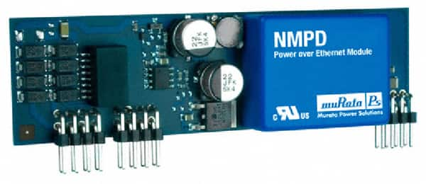
Designers can find a good variety of PoE board mount modules as well as off-board product. An example of the former is the Murata NMPD01 series, designed to extract power from Ethernet cables when sourced by PSEs also conforming to IEEE802.3af.
The company says the NMPD01 series removes the need for a localized equipment power source, significantly reducing installation costs. The IEEE802.3af standard allows for two power options, one on the data lines, and the other on the spare pair. The NMPD01 series can have voltage input on the data lines or spare pairs (Figure 3).

Figure 2: Murata’s power extraction modules have full functional compliance with IEEE802.3af.
The STMicroelectronics SPDCPOE05 is a power module specifically designed to provide an isolated, low-voltage power source to a remote powered device (PD) in PoE applications. It is designed to extract power from Ethernet cable when sourced by power sourcing equipment (PSE) also conforming to IEEE802.3af. According to the supplier, SPDCPOE05 is rated 10 W. In addition to a fully integrated dc/dc converter, each SPDCPOE05 power module incorporates internal input diode bridges to support both data line and spare line pair standard Ethernet connections, a transient suppressor for input over-voltage protection, and an EMI filter to ensure noise compatibility with Ethernet data signals. Other features include input under voltage lockout (UVLO), soft-start, over-current and short circuit protection.
As an example of an off-board/external device, consider Laird’s POE-24i, a power supply/power inserter that is autoranging on the input and has a regulated voltage output. It has overload and short circuit protection in addition to Ethernet surge suppression built-in.
Similarly, the SLPower (Ault/Condor) PW182RB is a self-contained 17 W (48 V @ 0.35 A) PoE Gigabit Ethernet injector with 10/100/1000 Mbps data rates and IEEE802.3af compliant detection. It can be located anywhere within 100 meters of the application (versus a separate power source that would need to be located within six feet). More information can be found in the SL Power Electronics POE product training module.
In control
PoE and PoE+’s simplicity make them relatively easy to set up. However, the silicon vendors have brought out a range of power management controllers to make implementation even easier.
Linear Technology’s LTC4264 is an integrated powered device interface controller for PoE and PoE+ applications up to 35 W. It is intended for use with the company’s dc/dc converters to power equipment on an Ethernet network.
According to Linear Technology, because the chip includes a precision dual current limit, the LTC4264 keeps inrush below the IEEE802.3af current limit levels. The LTC4264 includes a field-proven power MOSFET delivering up to 750 mA to the powered device load while maintaining compliance with the IEEE802.3af standard.
Complementary power-good outputs allow the chip to interface directly with a host of dc/dc converters. Linear Technology stated the LTC4264 provides a complete signature and power interface solution for powered device designs by incorporating the 25 kΩ signature resistor, classification circuitry, input current limit, undervoltage lockout, thermal overload protection, signature disable, and power-good signaling.
Linear Technology also offers a Power over Ethernet product training module providing useful information.
The Maxim MAX5942 integrates a complete power IC for powered devices in a PoE system. The chip comprises a powered device interface and a compact dc/dc PWM controller suitable for flyback and forward converters in either isolated or nonisolated designs.
According to Maxim, the chip’s interface complies with the IEEE 802.3af standard, providing the powered device with a detection signature, a classification signature, and an integrated isolation switch with programmable inrush current control.
The MAX5942 also includes all the building blocks necessary for implementing dc/dc fixed-frequency isolated power supplies. The company explains that the device is a current-mode controller with an integrated high startup circuit suitable for isolated telecom/industrial voltage range power supplies.
With the growing abundance of “always on” IP-based devices, Power over Ethernet is seen as a cost effective and, in many cases, necessary method of allowing these products to get power and data over existing cabling. For more information on PoE power supplies and controllers, use the provided links to product pages on the Digi-Key website.
References:
- http://en.wikipedia.org/wiki/PoE.
- Jeffrey Bausch, “PoE vs. PoE+,” Electronic Products, August 2011.
免责声明:各个作者和/或论坛参与者在本网站发表的观点、看法和意见不代表 DigiKey 的观点、看法和意见,也不代表 DigiKey 官方政策。


 中国
中国